.jpg)
Everything You Need to Know About Multimode Fiber Cable
Businesses today need fast, reliable networks. Multimode fiber works well for short to medium distances, providing scalable capacity and cost-effective deployment for data centers, office buildings, and campuses.
What is Multimode Fiber Cable?
Multimode fiber (MMF) is an optical fiber designed to carry multiple light propagation paths—or modes—simultaneously. This is made possible by its relatively large core diameter, typically 50 or 62.5 microns, compared to the ~9-micron core in single-mode fiber. The wider core accepts light from low-cost sources like LEDs or VCSELs, making it a more economical choice for systems where ultra-long reach is not a requirement.
MMF is optimized for shorter distances due to modal dispersion—variations in travel time among modes—which can broaden signals and limit data rate over long spans. Still, for most in-building or campus links up to several hundred meters, it delivers sufficient bandwidth at a lower total system cost than single-mode alternatives.
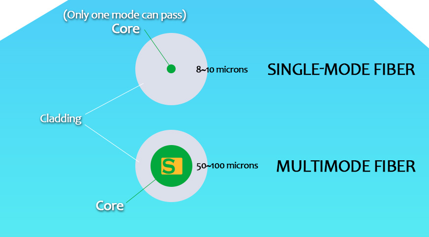
Structure of an Optical Fiber
Multimode fibers consist of three primary layers, each contributing to signal integrity and mechanical resilience:
Core
The core is the light-carrying region. In multimode fibers, the large core (50 μm or 62.5 μm) allows multiple light paths to travel simultaneously. This enables higher launch tolerance but also introduces modal dispersion over distance.
Cladding
Surrounding the core is a cladding layer with a lower refractive index. This contrast ensures that light is reflected back into the core, maintaining total internal reflection and guiding the signal down the fiber with minimal loss.
Coating
The outermost polymer coating protects the glass structure from physical stress and environmental exposure. It also helps preserve optical performance during installation and handling.
Advantages of Multimode Fiber Cable
Cost Efficiency
- Lower total system cost in LANs and data centers.
- Uses inexpensive transceivers like LEDs or VCSELs.
High Bandwidth for Short Distances
- Supports 10G–100G over typical building-scale spans.
- OM3/OM4 fibers optimized for 100–150 m links.
Simplified Installation
- Larger core diameter allows easier alignment.
- Reduces splicing and connectorization effort.
Flexible Integration
- Compatible with existing short-reach networking equipment.
- Ideal for retrofits and system expansions.
Scalability
- OM4/OM5 fibers support future upgrades without new cabling.
Types of Multimode Fiber
OM1, OM2, OM3, OM4, OM5 Specifications
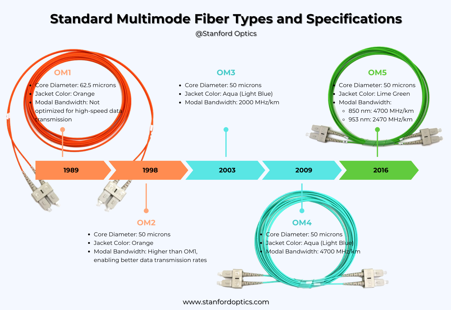
Multimode fibers are classified into OM (Optical Multimode) categories based on core diameter, bandwidth capacity, and performance with laser-based sources.
| Type | Core/Cladding Size | Bandwidth @850 nm | Maximum Distance (10 Gb/s) |
|---|---|---|---|
| OM1 | 62.5/125 μm | 200 MHz·km | ~33 m |
| OM2 | 50/125 μm | 500 MHz·km | ~82 m |
| OM3 | 50/125 μm (laser-optimized) | 2000 MHz·km | ~300 m |
| OM4 | 50/125 μm (enhanced) | 4700 MHz·km | ~400–550 m |
| OM5 | 50/125 μm (wideband) | Designed for SWDM | Similar to OM4 + wavelength division multiplexing |
Choosing the Right Type
-
OM1 / OM2: Still found in legacy buildings; not recommended for new high-speed deployments.
-
OM3 / OM4: Industry standard for 10G/40G/100G Ethernet in data centers.
-
OM5: Adds support for wavelength multiplexing (SWDM), enabling higher aggregate data rates without additional fiber strands.
When evaluating fiber type, consider not only current speed requirements but also the long-term bandwidth roadmap and compatibility with transceivers.
Applications of Multimode Fiber
Multimode fiber is best suited for high-speed, short-to-medium range connections. Key use cases include:
Enterprise Networks
Common in LAN backbones and intra-building links where data rates of 1G–10G are typical and cost efficiency is essential.
Data Centers
Used for top-of-rack (ToR) to core switch interconnects. OM4 is often preferred due to its higher modal bandwidth and longer reach.
Campus and Institutional Networks
Ideal for connecting multiple buildings across short outdoor distances using riser or armored cables, particularly where uptime and performance are critical.
Audio/Video Transmission
Reliable signal delivery with low latency makes MMF a fit for AV networks, media streaming systems, and digital signage infrastructure.
Security and Surveillance
Supports real-time, high-resolution video feeds across facilities with minimal signal degradation.
Other Environments
-
Healthcare: Linking diagnostic systems and data centers.
-
Manufacturing: Connecting control rooms to field devices in EMI-heavy environments.
-
Education: Backbone cabling for connected classrooms and labs.
Multimode vs. Single-Mode Fiber: Key Differences
While both multimode (MMF) and single-mode fibers (SMF) serve to transmit optical signals, they are built for distinct performance and distance profiles. Understanding how they differ is critical when planning a network infrastructure.
| Feature | Multimode Fiber (MMF) | Single-Mode Fiber (SMF) |
|---|---|---|
| Core Diameter | 50–62.5 μm | ~9 μm |
| Light Propagation | Multiple modes simultaneously | Single light mode |
| Light Source | LEDs or VCSELs (low-cost) | Laser diodes (higher precision) |
| Bandwidth | High for short distances | Very high, stable over long distances |
| Transmission Range | Up to 2 km (varies by OM rating) | 40–100+ km with minimal loss |
| Cost | Lower total system cost | Higher fiber + equipment cost |
| Use Case Fit | Data centers, LANs, buildings | Telco backbones, long-haul networks |
-
MMF is cost-effective for short links and easier to install due to its larger core and relaxed alignment tolerances.
-
SMF is the only viable choice for long-distance, high-speed data transmission. Though more expensive upfront, its performance over kilometers justifies the investment in wide-area networks and telecom infrastructure.
For many enterprises, MMF is the practical choice within a building or campus. SMF becomes necessary as distances increase or when planning for future 100G+ upgrades across larger geographies.
Read more: Single Mode vs. Multimode Fiber: Key Differences and How to Choose
Signal Attenuation Sources in Multimode Fiber
Signal degradation in multimode fiber is mainly caused by:
-
Absorption Loss – Impurities in the core absorb light and convert it to heat.
-
Scattering Loss – Microscopic density variations scatter light, especially at short wavelengths.
-
Bending Loss – Macrobends or microbends cause light to leak from the core.
-
Modal Dispersion – Different modes travel at slightly different speeds, spreading pulses over distance.
-
Cladding Mode Loss – Light escapes into the cladding due to poor splicing, connectors, or launch conditions.
Tip: Proper installation, quality connectors, and high-grade fibers (OM3–OM5) reduce these losses.
Launch Conditions
How light enters a multimode fiber—known as the launch condition—has a major impact on signal quality. Poor launch alignment can increase modal dispersion and signal loss.
Launch Types:
-
Undersized Launch – Light enters only part of the core. This reduces modal dispersion slightly but underutilizes available bandwidth.
-
Oversized Launch – Light spreads too widely or misaligned, exciting high-order modes unevenly. This causes modal noise and signal distortion.
-
Equilibrium Launch – Ideal condition where mode power distribution matches what naturally occurs along the fiber. Achieved using mode conditioning or overfilled launch (OFL) sources.
Best Practices:
- Center the light source (LED or VCSEL) on the fiber core.
- Use mode conditioning cords for consistent testing.
- Avoid mechanical stress at connectors to prevent microbending.
A controlled launch ensures predictable performance, especially for high-speed multimode networks like 40/100 G over OM4 or OM5 fibers.
Installation and Maintenance
Multimode fibers are easier to install than single-mode, but proper handling is still essential for reliable performance.
Installation Tips:
- Core alignment: Larger cores (50–62.5 µm) allow more tolerance, but always center connectors carefully.
- Connector types: LC, SC, and ST are common; LC works best for high-density setups.
- Bend radius: Avoid tight bends; follow manufacturer specs to prevent macrobending loss.
- Termination options: Use field-installable connectors or pre-terminated assemblies as appropriate.
Maintenance Best Practices:
- Regular inspections: Check patch panels, enclosures, and connectors for damage.
- Cleaning: Dust or oil on end faces can degrade signals; use lint-free wipes and fiber-specific cleaners.
- Document runs: Keep accurate cable maps and test results for troubleshooting.
- Periodic testing: Monitor signal integrity with OTDR or power meters.
- Protect slack loops: Use trays or enclosures to prevent crushing or tangling.
Following these guidelines ensures consistent performance and longevity of multimode fiber networks, particularly in data centers and enterprise environments.
Conclusion
Multimode fiber provides a balanced combination of bandwidth, cost, and easy deployment, making it ideal for enterprise, campus, and data center networks. Core diameters optimized for shorter distances deliver fast connections without the complexity or cost of long-haul single-mode systems.
From OM1 to OM5, each grade meets different performance needs. Choosing the right type and understanding its physical and optical properties ensures long-term network stability.
Stanford Optics offers a wide range of multimode fiber cables and connectivity components for 1G, 10G, 40G, and 100G applications, including OM1–OM4 with various jacket types and configurations to fit diverse deployment scenarios.
Frequently Asked Questions (FAQs)
Q: What is the transmission range of multimode fiber?
Multimode fiber is designed for short- to medium-distance networking. For 10 Gigabit Ethernet, it can reach up to 550 meters, while Gigabit Ethernet spans roughly 2 km. This makes multimode fiber ideal for data centers, enterprise LANs, and campus networks.
Learn More: For detailed insights, check out How Far Can Multimode Fiber Optic Cables Transmit.
Q: How does multimode fiber compare to single-mode fiber?
Multimode fibers have larger core diameters, support multiple light modes, and are generally less expensive for short-distance applications. In contrast, single-mode fibers have smaller cores, support only a single light mode, and are suited for long-distance and high-bandwidth transmissions.
Q: What types of multimode fiber are available?
Multimode fibers are categorized into OM1, OM2, OM3, OM4, and OM5, each with varying bandwidth and distance capabilities to suit different networking needs.
See: OM1 vs OM2 vs OM3 vs OM4 vs OM5: Multimode Fiber Cable Types.
Q: Is multimode fiber suitable for long-distance transmissions?
While multimode fibers excel in short to medium-distance applications, they are not typically recommended for long-distance transmissions due to higher attenuation and modal dispersion compared to single-mode fibers.
Q: What are the cost considerations when choosing multimode fiber?
When opting for multimode fiber, consider factors such as the initial cost of fibers and components, installation expenses, and long-term maintenance. Multimode fibers are generally more cost-effective for shorter distances and high-bandwidth requirements within budget constraints.

