.jpg)
Optimizing Optical Module Performance
1. Optical Modules 101: What Are They, Anyway?
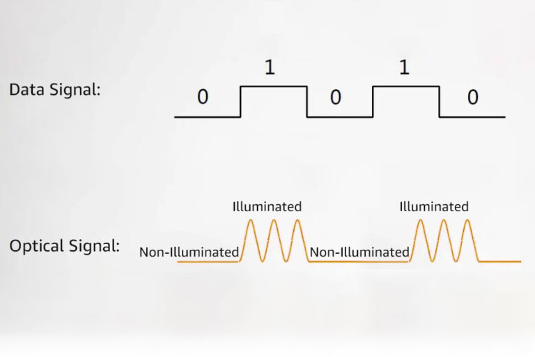
Think of optical modules as the “translators” of the fiber-optic world. They convert electrical signals (from your router/switch) into light pulses (for fiber cables) and vice versa.
Transmitter Side: An electrical signal hits a laser diode (LD) or LED, which spits out light. The stronger the signal, the brighter the light.
Receiver Side: Light enters a photodetector (like a tiny solar cell), which turns it back into electricity. A built-in amplifier boosts the signal for your device to read.
Key Components:
- Optoelectronic devices (lasers, detectors)
- Driver/control circuits (think of them as the “brain”)
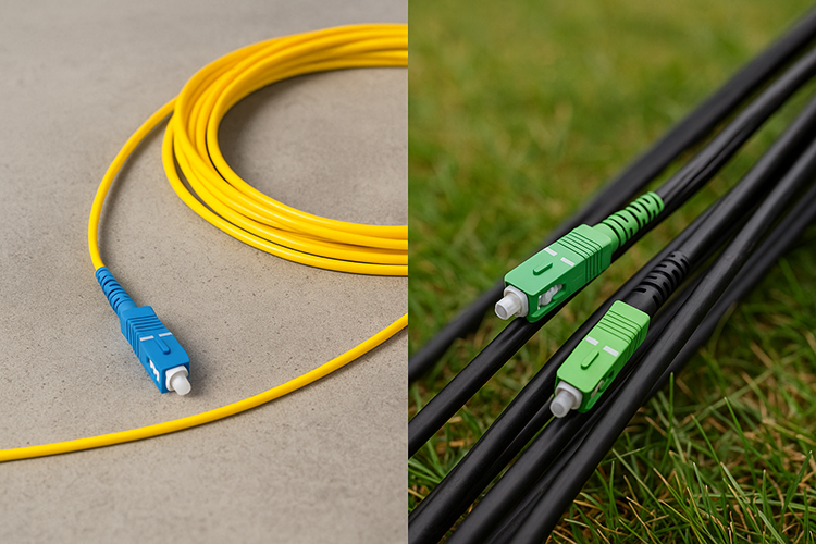
- Optical connectors (the plugs that click into your fiber cables)
2. The 5 Metrics That Matter Most
When evaluating optical modules, these numbers tell you if they’ll perform under pressure (or choke at the first sign of trouble):
Transmitter Metrics
Average Optical Power: How bright the light is (measured in dBm). Too dim? Your signal gets lost in the fiber. Too bright? You risk damaging receivers.
Extinction Ratio: The difference between “on” (1) and “off” (0) light power. A higher ratio = cleaner signals (typical range: 8.2–10 dB).
Center Wavelength: The “color” of light (e.g., 850nm for short-range, 1550nm for long-haul). Match this to your fiber type!
Receiver Metrics
Overload Power: The max light intensity the receiver can handle before freaking out (leading to errors).
Receiver Sensitivity: The faintest light the receiver can detect (lower dBm = better sensitivity).
Dynamic Range: The gap between sensitivity and overload power. Wider range = more flexibility in real-world conditions.
3. Why doesn’t My Signal Reach 10km like the Spec Sheet Says?
Three villains are lurking in your fiber:
- Optical Loss: Light gets absorbed, scattered, or leaked as it travels. Dirty connectors? Bent cables? Expect higher losses.
- Chromatic Dispersion: Different wavelengths travel at slightly different speeds, causing signal “smearing” (especially at high speeds).
- The Simple Formula:
Max Distance = (Transmit Power – Receiver Sensitivity) / Fiber Attenuation
Example: If your module has -3dBm transmit power, -24dBm sensitivity, and fiber loses 0.4dB/km, you get ~52.5km (before dispersion kicks in).
4. How to Supercharge Your Module’s Speed
Need faster data rates without ripping out your infrastructure? Try these tricks:
A. Multiply Wavelengths (WDM Technology)
CWDM: Cheap and simple, but limited to ~8–16 channels (20nm spacing).
LWDM: Narrower spacing (4nm) for more channels in the O-band.
SWDM: Short-wave multiplexing for 850–950nm (great for data centers).
B. Go Parallel (Multi-Lane Fiber)
Use MPO connectors to bundle 4/8/12 fibers, each carrying the same wavelength.
Example: QSFP28 SR4 = 4 lanes x 25G = 100G over 100m (OM4 fiber).
C. Upgrade Your Modulation (PAM4)
Traditional NRZ sends 1 bit per symbol (0 or 1).
PAM4 sends 2 bits per symbol (00, 01, 10, 11), doubling speed.
Used in 50G/100G/400G modules (e.g., 400G QSFP-DD SR8 = 8 lanes x 50G PAM4).
5. Why High-Performance Modules Are a Big Deal for AI/Big Data
Imagine trying to stream 4K video on a dial-up connection—that’s what AI training feels like with slow optical modules. High-performance modules deliver:
- 400G/800G+ speeds (because waiting is for suckers)
- Low latency (critical for real-time analytics)
- High density (fit more bandwidth into the same rack space)
- Energy efficiency (save on power bills and carbon footprints)
Final Thoughts: Don’t Overpay for “Vaporware” Specs
Not all optical modules are created equal. Some vendors cut corners on components or testing, leading to unreliable performance. At Stanford Optics, we:
- Source premium optoelectronic chips (no off-brand lasers here).
- Test every module in real-world conditions (not just a lab bench).
- Offer custom solutions (because “one size fits all” is a lie).
Need help picking the right module? Contact us right now!

